In order to make a current days typical fuel cell MEA you will require some materials. These materials can either be ordered in our webshop or can be prepared by yourself.
An MEA is no more than a stack of 2 electrodes separated by a proton conducting membrane. Currently we mainly use 2 types of MEA namely CCM or GDE based MEA’s
CCM
CCM, which stands for catalyst coated membrane, can be made by various procedures:
Decal transfer, which is a process where catalyst material is first deposited onto a carrier film. From this carrier film the catalyst layer is adhered to the membrane mostly by heat
Direct deposition, where catalyst material is directly deposited onto the membrane
Both processes have their advantages and disadvantages. The main advantage of decal transfer is the freedom to use various GDL types, sligthly lower proton resistivity, whereas a typical disadvantage is the lengthy process. For direct deposition an advantage is the shortened process and superior adherence of catalyst material to the membrane which is also a disadvantage. The solvent typically used to disperse the catalyst material in is also a solvent to the membrane, deforming and partially dissolving the membrane.
GDE
GDE, which stands for gas diffusion electrode, is the other type of MEA. To prepare a GDE catalyst ink or slurry is directly deposited onto the GDL (gas diffusion layer). The main advantage of this process is that it is fairly simple to achieve, in theory you only need a brush, the dispered ink and an oven to engage within this process. A disadvantage of this process is that the MEA comes with a slightly higher proton resistivity due to less contact of the catalyst with the membrane.
Membrane
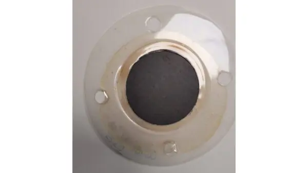
Depending on the type of membrane, the thinner types of membranes are often encased between 2 plastic films. Prior to usage of for these membranes, the films need to be removed. Removing these layers can be challenging. First the orientation of encased membrane needs to be determined, this is because of the difference in difficulty of removing these layers. One layer is significantly thicker that the other, making it more difficult to remove this layer. An often used and easy way to determine this is to look for how it orientates after it has been cut. The cut-off membrane will usually curl up the top layer will be the thinner plastic protective film layer, which is easier to peel off. When peeling off it can occur that the membrane layer adheres to the protective film. In order to ensure succesful separation of the membrane from its protective layers a drop of de-ionised water could be used. Either rub or drop this droplet of water on the suspected membrane material, if the material swells it is membrane, if it doesn’t it is protective film. Please make sure to use the water droplet only outside your envisioned active area. Deformation of the membrane prior to use creates another variable in your experiment.
Having peeled of the membrane the MEA can be formed where the GDL or GDE is placed on the membrane. Typically it is the most black layer of the GDL or GDE that should be facing the membrane as that is the layer with either the catalyst or the micro porous layer (MPL).
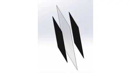
Before creating a MEA, write on one side of the membrane anode or cathode. Do this before making the CCM or before placing GDE’s. For pens a water proof thin line marker is recommended to use or instead of writing down a nick out of centre in one of the sides.
Step by step GDE based
- Cut out a anode GDE
- Cut out a cathode GDE
- Cut out a membrane (and peel off membrane if applicable)
- Mark the membrane for anode or cathode
- Place the anode GDE on the anode flowfield of the cell plate facing the catalyst upwards
- Place the membrane over the GDE
- Place the cathode GDE, catalyst facing downwards, exactly over the anode GDE
- Place the cathode cell plate, flowfield facing downwards on top of the MEA
- Compress the cell plate and MEA
Step by step CCM based
- Cut out a anode GDL
- Cut out a cathode GDL
- Cut out a CCM (CCMs should always already be marked anode or cathode)
- Place the anode GDL on the anode flowfield of the cell plate facing the MPL upwards
- Place the CCM with the cathode catalyst facing upwards over the GDL
- Place the cathode GDL, MPL facing downwards, exactly over the anode GDL
- Place the cathode cell plate, flowfield facing downwards on top of the MEA
- Compress the cell plate and MEA